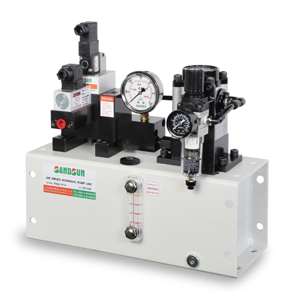
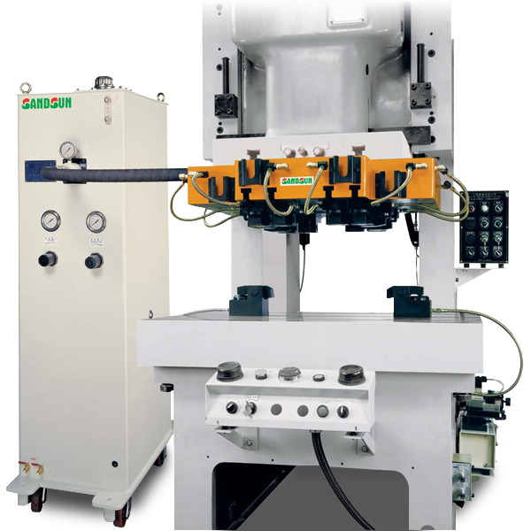
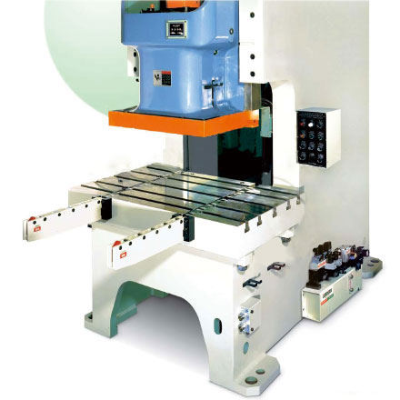
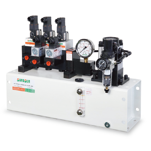
Air Driven Hydraulic Pump Unit
Quick Die Change System
Selection Guide
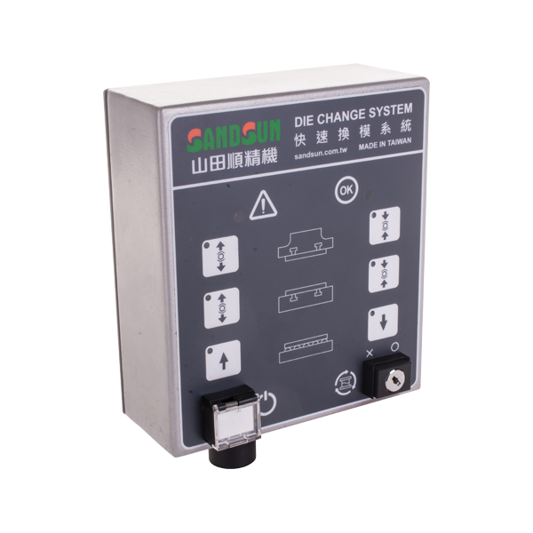
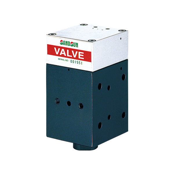
The Choice of Air Driven Hydraulic Pump Unit
|
Number of Circuit |
Choice & Standard | Control Model |
|---|---|---|
| 1 | Single. For the operation of the die clamp on teh upper or lower die. | NO |
| 1 | The operations of the upper and lower die clamps use the same circuit. | NO |
| 1 | Single. For the operation of the die lifter. | NO |
| 2 | Separated circuit operation for upper and lower die clamps | NC |
| 2 |
The same circuit operation for upper and lower die clamps. One circuit is for the operation of the die. lifter. |
NO NC |
| 3 |
Separated circuit operation for upper and lower die clamps. One circuit is for the operation of the die lifter. |
NO NC |
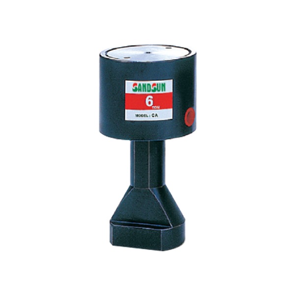
The Choice of Die Clamp
| MODEL |
|---|
|
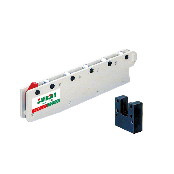
CA: The template with the U cuts CB: The template with no the U cuts |
| Choice Standard | ||||||||||||||
|---|---|---|---|---|---|---|---|---|---|---|---|---|---|---|
Lower die (Σ F2)=ΣFx40% Lower clamp F=ΣF2 / n (tons)
|
The Choice of Die Lifter
| MODEL |
|---|
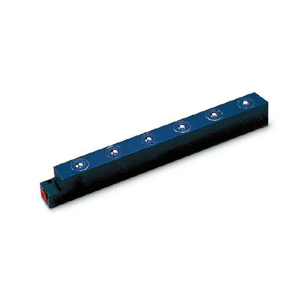
| DL/DB/DS/DLS |
| Choice Standard |
|---|
|
The Choice of Die Arm
| MODEL |
|---|
| RC/RD/RE/RF/RS |
| Choice Standard |
|---|
|
Copyright © Sandsun Precision Machinery Co., Ltd. PRM Taiwan , Design by Polaris
